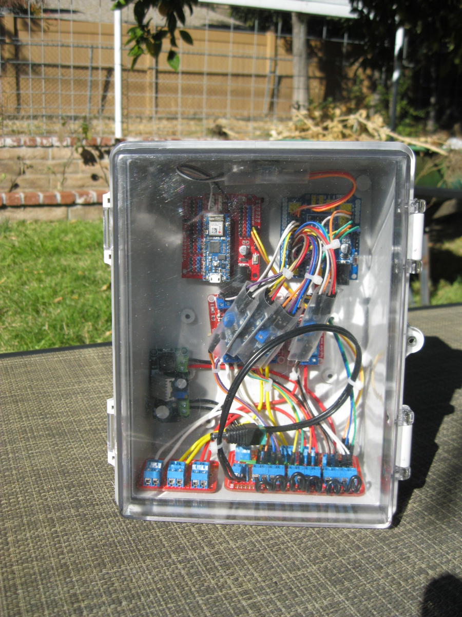
3PI Expert Controllers™
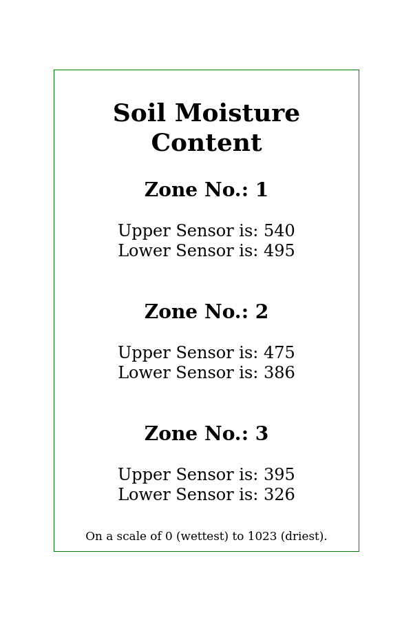
Irrigation cycles automatically adjust to the changing needs of the plants or trees being monitored.
The ability to maintain the moisture content in the soil for each plant, in a collection of plants, allows us to compare and contrast the differences that result from different planting times and adjustments to other variables, in order to develop best practices for a changing world.
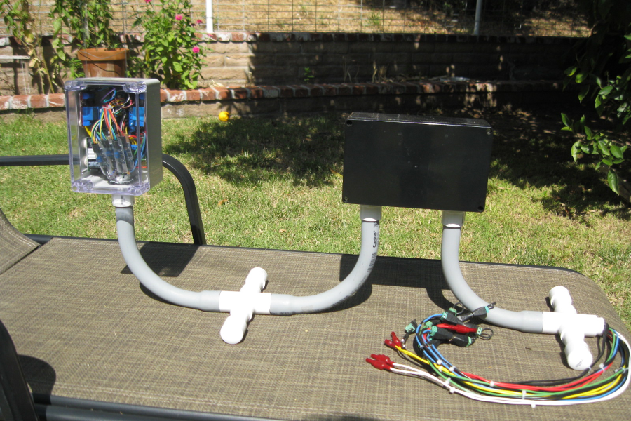
The image above is of a 3PI Three-Zone Expert Controller.™